Ferr2D reference
Index
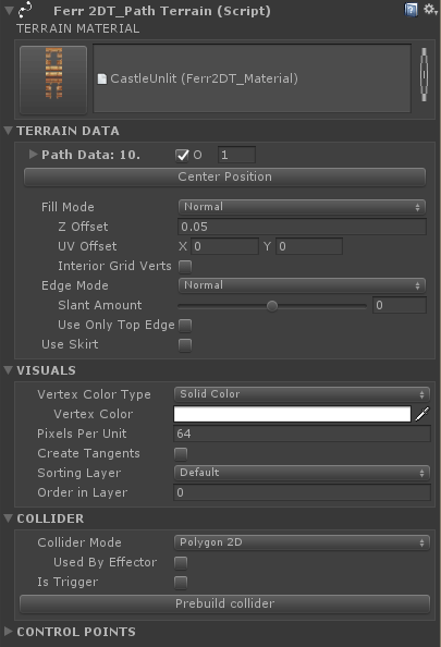
- Ferr2DT_PathTerrain Component
- TERRAIN DATA
- Path Data
- Center Position
- Fill Mode
- Fill - Z Offset
- Fill - UV Offset
- Fill - Invert Fill Border
- Fill - Interior Grid Verts
- Edge Mode
- Edge - Slant Amount
- Edge - Use Only Top Edge
- Use Skirt
- VISUALS
- COLLIDER
- Ferr2D Material Editor
Ferr2DT_PathTerrain
Most of Ferr2D happens on this component here! To keep your inspector cleaner, a number of the properties will hide themselves when they're not relevant. Your particular inspector may look slightly different as a result.
- TERRAIN MATERIAL
- Clicking the button to the left will bring up the Terrain Material selector that includes a list of recently used materials. The right side is a standard Unity object selector that will highlight the current terrain material when clicked, or open Unity's asset selector.
- TERRAIN DATA
- Path Data
- Closed
- Sets the path to closed or open.
- Split Distance
- How detailed should the curves be? This represents the spacing of the samples, so lower means more detail. If you're trying to reduce the number of vertices, or improve scene sizes, keep this as high as possible without losing quality.
- Closed
- Center Position
- Shifts the object's origin to the center of the terrain. You'll notice the position widget change when you press this. Alternatively, you can drag select all the control points, and shift the terrain around to more specifically control the origin.
- Fill Mode
- Fill Mode - Normal
- The terrain will add a fill mesh inside of the path.
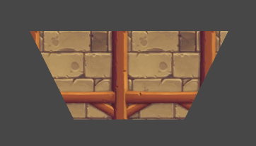
- The terrain will add a fill mesh inside of the path.
- Fill Mode - Invert
- The terrain will add a fill mesh outside of the path.
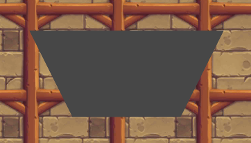
- The terrain will add a fill mesh outside of the path.
- Fill Mode - None
- There will be no fill mesh at all!
- There will be no fill mesh at all!
- Fill - Z Offset
- The fill mesh is offset by a small amount to help avoid Z-fighting. The default value of 0.05 is recommended, and shouldn't need to be changed often.
- The fill mesh is offset by a small amount to help avoid Z-fighting. The default value of 0.05 is recommended, and shouldn't need to be changed often.
- Fill - UV Offset
- The texture coordinates of the fill mesh are based on the world coordinates, and offset by these values. If you have a texture that you want to line up with something, or just don't like where your fill texture is lining up, try shifting it here!
- The texture coordinates of the fill mesh are based on the world coordinates, and offset by these values. If you have a texture that you want to line up with something, or just don't like where your fill texture is lining up, try shifting it here!
- Fill [Invert Mode] - Invert Fill Border
- When these values are zero, Ferr2D automatically calculates a border to extend the inverted fill mesh out to. If you don't like the default border, set your own values here!
- When these values are zero, Ferr2D automatically calculates a border to extend the inverted fill mesh out to. If you don't like the default border, set your own values here!
- Fill - Interior Grid Verts
- Adds extra vertices to the interior of the grid mesh. This is useful for texture blending/painting, vertex lighting, and certain Vertex Color modes.
- Grid spacing - How far apart the interior vertices are spread out.
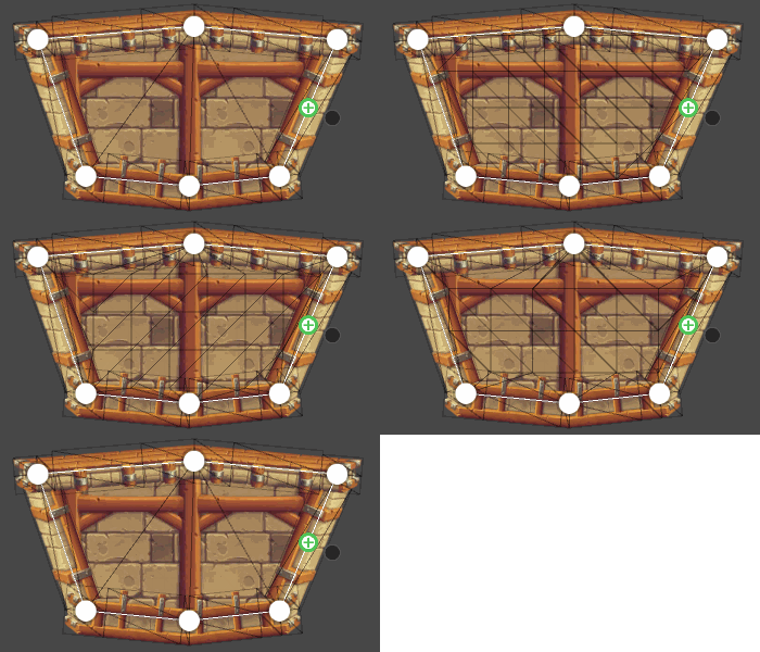
- Fill Mode - Normal
- Edge Mode
- Edge Mode - Normal
- The terrain will add an edge mesh along the path.
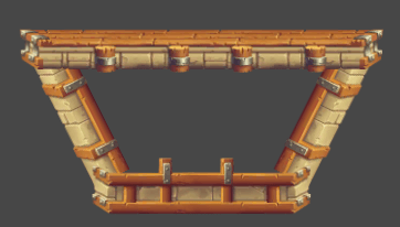
- The terrain will add an edge mesh along the path.
- Edge Mode - Invert
- The terrain will add an edge mesh along the path, but will flip the edges inside out. This pairs well with the Fill Mode Invert for interior spaces.
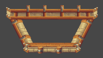
- The terrain will add an edge mesh along the path, but will flip the edges inside out. This pairs well with the Fill Mode Invert for interior spaces.
- Edge Mode - None
- There will be no edge mesh at all! Colliders will now ignore any edge rules in the Terrain Material, and will follow the path exactly.
- There will be no edge mesh at all! Colliders will now ignore any edge rules in the Terrain Material, and will follow the path exactly.
- Edge - Slant Amount
- This affects the z-values of the terrain edge, adding a slant to it! It can be handy for adding a subtle parallax effect to the edge.
- This affects the z-values of the terrain edge, adding a slant to it! It can be handy for adding a subtle parallax effect to the edge.
- Edge - Use Only Top Edge
- Forces the terrain to only use the top edge defined in the Terrain Material, without any corners or breaks in the mesh! This is excellent for pipe or plant type terrain materials.
- Forces the terrain to only use the top edge defined in the Terrain Material, without any corners or breaks in the mesh! This is excellent for pipe or plant type terrain materials.
- Edge Mode - Normal
- Use Skirt
- Simplifies terrain creation if all you care about is the top edge! It adds two invisible vertices to the ends of the path, offset by Skirt Y Value to create the bottom of the terrain.
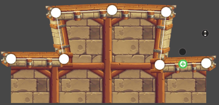
- Simplifies terrain creation if all you care about is the top edge! It adds two invisible vertices to the ends of the path, offset by Skirt Y Value to create the bottom of the terrain.
- Path Data
- VISUALS
- Vertex Color Type
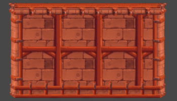
- Solid Color
- Mesh vertices are set to a single color, this allows you to tweak and tint your terrain for lighting and variety while still letting Unity batch your materials for performance! Make sure you use a shader that supports vertex colors to take advantage of this.
- Gradient
- Mesh vertices are set to a color gradient along an angle. This can be useful for indicating light, color, or shadows in a particular direction.
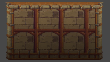
- Distance Gradient
- Mesh vertices are set to a color gradient based on their distance from the path. This is excellent for doing fog-of-war style shading on the terrain. You may want to activate Interior Grid Verts for this feature to work well.
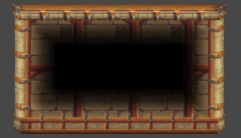
- Preserve Vert Color
- Primarily for vertex painting or light baking! This will do its best to preserve vertex colors through terrain edits, so any vertex painting you've done doesn't get wiped when you update the terrain.
- Pixels Per Unit
- The easiest measure for ensuring consistent pixel density. How many pixels should Ferr2D attempt to fit into one unit of Unity space? This isn’t always exact, but it’s a target that Ferr2D strives towards.
- Create Tangents
- If you're using a material with normal maps, you'll need Ferr2D to generate tangents! Generating tangents is a little expensive in the editor though, so it's not enabled by default.
- Sorting Layer and Order in Layer
- These are the same as the Unity Sprite's attributes, and helps you to integrate with those sprites better!
- Collider Mode
- None
- No colliders, this terrain is a visual object only!
- Polygon 2D
- Creates a Polygon Collider 2D per Physics Material specified in the Terrain Material.
- Edge 2D
- Creates an Edge Collider 2D per each edge segment.
- Mesh 3D
- Creates a 3D Mesh Collider per each edge segment. The Z-axis length is specified by the Collider Depth property.
- Used By Effector
- Collider 2D components have a Used By Effector attribute, this sets it when the colliders are generated!
- Is Trigger
- Collider components have an Is Trigger attribute, this sets it when the colliders are generated!
- Physics Material [Edge Mode - None]
- Normally the physics material is pulled from the Terrain Material's edge data, but if we aren't using any edges, you must specify the physics material here!
- Prebuild Collider
- If want Ferr2D to build colliders in the editor instead of on start, or want to have a pass at them after they're built, click this button! Ferr2D will keep them up-to-date as you modify your terrain. If you're switching Collider Modes after you've prebuilt collders, it's recommended that you delete the collider components first.
Ferr2D Terrain Material Editor
The Terrain Material describes how materials are applied to the Path Terrain. You can define a single edge using the "top" edge in order to achieve things like pipes, plants and branches, or you can define all 4+ to create a regular terrain material. Check out some of the example materials to see what sort of things you can create with it!
For video tutorials of this, check out these:
http://youtu.be/_V9v2RXkUog
http://youtu.be/TYQSuhsyCDE
- Edge Selector
- Select or create edges for the current terrain material. Top, Left, Right, and Bottom edges are Ferr2D's automatic edges, determined by the angle of their path segment. Additional edges are accessible in the scene view through the edge override handles.
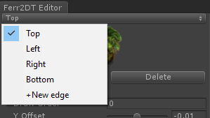
- Select or create edges for the current terrain material. Top, Left, Right, and Bottom edges are Ferr2D's automatic edges, determined by the angle of their path segment. Additional edges are accessible in the scene view through the edge override handles.
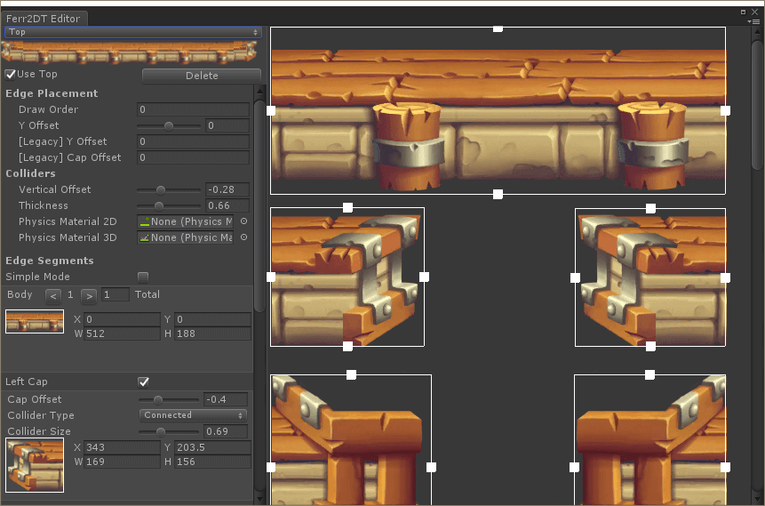
- Edge Placement
- Draw Order
- This is a number that indicates the draw order of the edges, where lower draws earlier! It also offsets the edge by a very small amount (+Z) to avoid Z-fighting. I typically use 0 for the top, 2 for the sides, and 1 for the bottom.
- Y Offset
- This will offset the edge mesh from the path by a certain amount. This can be extremely helpful for lining up edge materials better. The value is multiplied by the edge's height.
- Colliders
- Vertical Offset
- This will offset the top of the collider from the top of the edge. The value is multiplied by the edge's height.
- Thickness
- This will offset the bottom of the collider from the top of the collider. The value is multiplied by the edge's height.
- Physics Material 2D
- Used when generating 2D colliders, this physics material gets assigned to the colliders representing this edge.
- Physics Material 3D
- Used when generating 3D mesh colliders, this physics material gets assigned to the colliders representing this edge.
- Edge Segments
- Simple Mode
- Enables a simplified mode of interacting with the Terrain Material. This only works under specific texture layouts, but it's an easier interface when you can!
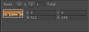
- Body
- The "body" of this edge is the segment of the Edge Material that will be repeated along the bulk of the path.
- X,Y,W, and H are measured in pixels from the top left corner of the texture. These are stored as UV coordinates internally, so if you resize the texture, they will resize with the texture.
- By increasing the "Total" property, you may have multiple body segments for the tool to randomly choose from when generating the mesh.
- Use the < and > arrows to pick the active body segment for the editor.
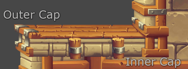
- Caps (Left, Inner Left, Right, Inner Right)
- Caps are small texture segments that are placed at the end of each edge to cap it off. These are optional. They also contain collision information, so you can customize how your caps behave physically. Inner Left and Inner Right are caps that are applied at inner coners (exterior angle is less than 180) whereas Left and Right caps are applied at outer corners (exterior angle is greater than 180).
- Cap Offset
- This will allow you to adjust where the cap meshes are at the end of their segments. This can also help with lining up edge materials.
- Collider Type
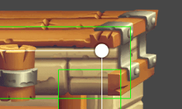
- Rectangle
- Simple, sharp corners, probably good for most cases. Can result in spurs that stick out sometimes, if this is a problem, try the Connected type.
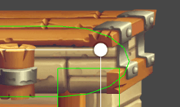
- Circle
- Maybe more of an oval, but y'know. If you're looking for a more organic or smoothed corner, this may fill your needs.
- Connected
- The top of the cap extends using the Collider Size, and the lower part attempts to connect to the adjacent edge's collider. This can make collider joins much smoother, and eliminate spurs on the collider. It is designed to be used with rectangle caps for adjacent edges.
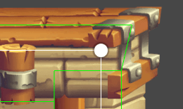
- Connected Sharp
- Same as the Connected cap, and the top of the cap ends at the intersection of the top edge of the adjacent collider edge. This creates a sharp corner that will maintain a continuous flat edge along both sides. Note that the sharp behaviour can created undesired spikes at extreme angles.
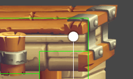
- Intersect Sharp
- Intersects the top edge with the adjacent top edge, and the bottom edge with the adjacent bottom edge! Similar to Connected Sharp, but changes the distribution of the collider shape. This can be important when assigning different physics materials to different edges. Note that the sharp behaviour can created undesired spikes at extreme angles.
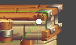
- Intersect Top and Intersect Edge
- Similar to Intersect Sharp, but preserves the top edge's Collider Size. It also attempts to keep the transition from edge to top as smooth as possible, without going outside the bounds of the given parameters. Use Intersection Top for the edge you wish to preserve Collider Size with, and Intersection Edge for the edges that interact with it.
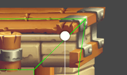
- Collider Size
- How far down the cap does this collider extend? This is multiplied by the cap's width.

